Intersight Managed Mode (IMM) is Cisco’s excellent tool for deploying and managing Hyperflex & UCS Domains (including, and especially UCS-X) from the Cisco SaaS portal.
Being cloud based, IMM allows multiple UCS Domains and Servers to be managed from a single management plane and share common policies (think UCSC in the cloud), potentially reducing overhead and definitely being more intuitive. IMM encourages the re-use of policies cross domains and geographical regions, therefore reducing operational overhead, increasing uniformity, and reducing errors made when recreating settings for different domains.
IMM completely replaces UCSManager (UCSM), the Fabric Interconnect (FI) on-board domain management tool, which does not exist when the management mode (explained in the next section) chosen during setup is set to Intersight. IMM is not inline however, and should the domain become disconnected from the internet, a managed UCS Domain will continue to function.
The functions described in this guide require at least the essentials licence for intersight, however the base version of Intersight FOC, albeit with limited capabilities. It is highly recommended that if the advanced features are not required, the base version provides excellent global visibility & functionality for an FOC tool.
Browse to www.intersight.com to get started.
P.S. This is a lengthy post, you might want to get coffee.. or some RedBull.
Introduction to Policy, Pool, and Profile Maps
The following flow charts define route to deploying a new UCS Domain using IMM, it’s worth remembering that apart from claiming the device, most of the policies and profiles required are the same as a traditional UCSM Domain.
The policies and profiles required to consume and operate UCS Domain and Service Profiles are also mapped, they define the vast majority of the pools, profiles and policies required/recommended for either a base UCS Domain or Service Profile (used to consume blades).
The policies are similar between Servers (Standalone), Servers (FI Attached) and Blade Chassis however there are nuances between them, this guide’s focus is on domains Servers which are FI Attached (being an IMM Guide).
There are lots of policies, pools and profiles required to correctly deploy a UCS Domain (see Appendix C for a breakdown), during the setup of Templates, Service Profiles, Domain Profiles etc, you will have the opportunity to either select an existing policy or pool, or create a new one. The wizards are very intuitive, and there is no reason to create all the policies up front if this is the first domain or server.
The nodes within each map are colour coded:
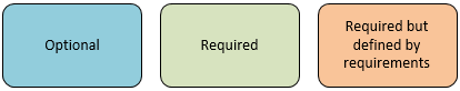
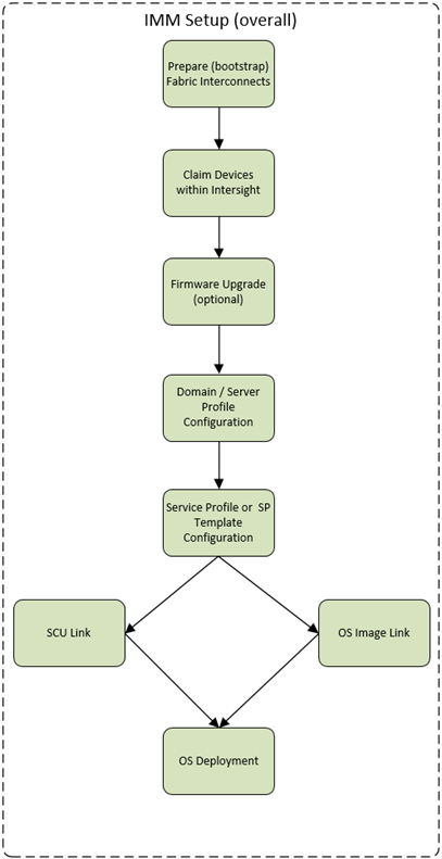
IMM Overall Setup Flowchart
The following diagram describes the overall process for setting up an IMM domain and consuming the resources
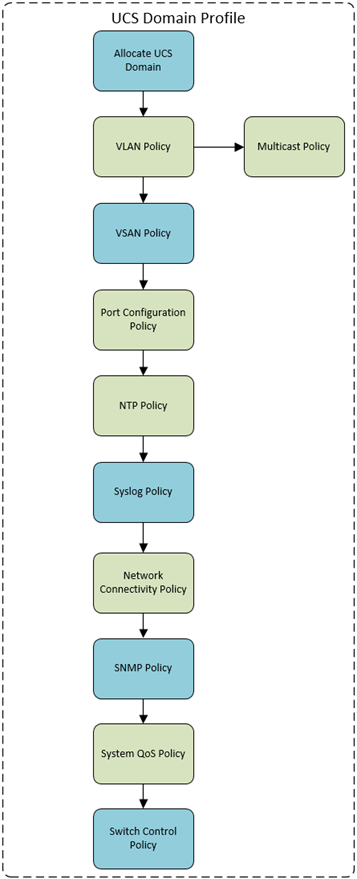
UCS Domain Policy Map
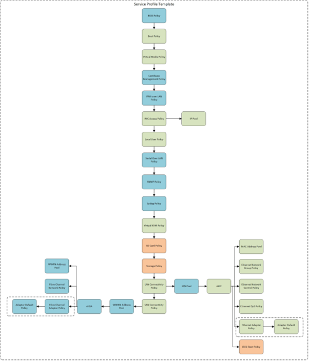
Service Profile Template Map
Step 1: Prepare (bootstrap) the FI to be claimed
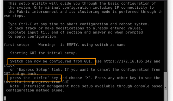
When setting up the FI’s to be managed by Intersight via IMM, we must connect to the console and select ‘Console Setup’ and NOT GUI. Press CTRL-C and X.
Detailed steps are described below, these visuals are provided for illustration purposes due to the importance of this step, deviating from these guidelines will result in delayed deployment due to resetting the configuration on the FI’s.
First you might need to halt the GUI configuration.
The following provides an illustration of how to setup the Fabric Interconnects to be setup via the CONSOLE, and setup the management mode as INTERSIGHT.

- You will be asked to enter the configuration method. Remember that IMM can only be configured through the console, so type console.
- For the management mode, type Intersight to choose IMM rather than UCSM.
- The wizard will ask you to confirm that you are setting up a new fabric interconnect in Intersight Managed Mode. Type ‘y‘ to confirm.
- You will be asked whether to enforce strong passwords. Obviously, strong passwords are encouraged. Type y to enforce strong passwords.
- For the switch fabric (A or B), choose which FI this is, assuming this is A.
- You should have received IP addresses for your lab via email or Webex. Ensure you select the addresses intended for your pod. Enter the IP address for FI-A.
- Enter the netmask for the management network (example 255.255.255.0).
- Enter the default gateway.
- Enter the IP address of the DNS servers.
- Type yes to configure the default domain name.
- Set the default domain name to suit the environment
- The last step is to confirm all your settings. Verify your settings are correct and type yes to continue.
For the other FI
- You may need to hit enter to wake up the console for FI-B. If you see nothing on the screen, the FI might be waiting for the user to either configure it from the GUI or press CTRL-c to interrupt. Just like you did for the FI-A setup, press CTRL-c.
- Just like you did for the FI-A setup, press x and then enter. As with FI-A, you may not actually see the “x” when you type it.
- For the configuration method, enter console. Remember that IMM can only be configured through the console.
- FI-B will detect that it’s peer (FI-A) is already configured and will ask if it should attempt to join that cluster. Type y and hit enter.
- Enter the password you used for FI-A
- If the Fabric Interconnects are running firmware 4.1.3b, you will see a message asking if you want to update firmware on this fabric interconnect to the peer’s version. Type y and wait for the fabric interconnect to update (5-10 minutes). This is only an issue in this specific firmware release. If you do not see this message, proceed to the next step.
- At this point, FI-B will pull the networking configuration from its peer. You only need to provide FI-B with an IP address. Use the IP address provided in the worksheet.
- Type yes to save the configuration and restart the fabric interconnect.
Claiming the device with Intersight
When you were following the previous section of bootstrapping the Fabric Interconnects, what you will notice is that we didn’t provide a VIP Address for the UCS Manager (UCSM), this is because there is no UCSM when using IMM, Intersight connects to both FI’s via the local IP’s (albeit using an outbound connection from the FI).
To configure some basic settings to make the box ready for connecting to the internet, you can connect to EITHER of the Fabric Interconnect IP Addresses:
- Open the web browser in this jump host and browse to the IP address of either fabric interconnect using HTTPS. You will see the Device Console login screen like the one shown below

- Ensure you use HTTPS or you will be unable to connect to the Device Console.
- Use the credentials you configured earlier during fabric interconnect console setup to log in, if you get a red box with ‘Error:500’ or similar it’s normal until you enter the NTP Servers. Eventually you should see something like the below image:

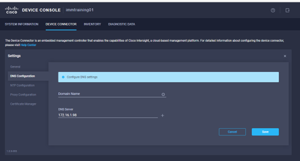
- Go to the Device Connector tab and click settings.
- Check the DNS Servers are correct
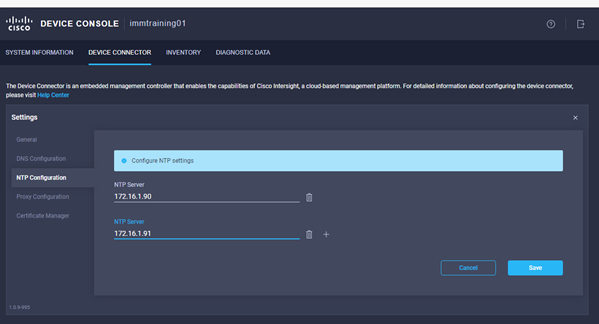
- Go to the NTP Configuration section and enter the NTP servers captured in the deployment worksheet, click save.
- Enter a Proxy Server if required.
- The images below have been included to demonstrate the steps:

- Go to the Device Connector tab. If there is an error on this page saying “Some unknown internal error has occurred” this is likely because you skipped setting NTP on the previous step or you simply got to this step before the fabric interconnects have fully initialized. Please click the refresh button in the device connector view, but if the problem persists, reach out to TAC to address this. If instead you see a screen like the one shown below (which shows that the fabric interconnect can connect to Intersight but is not yet claimed), then proceed to the next step.

- Make a note of the Device ID and Claim Code, then browse to https://intersight.com from a web browser. Use the credentials for an account with Enterprise Admin, Device Technician or other role which can add HW.
- Click the blue Claim Target button in Intersight (top right).

- For target type, select Cisco UCS Domain (Intersight Managed) as shown below and click the Start button. YOU HAVE 10 Minutes to perform this step (or the claim code changes)
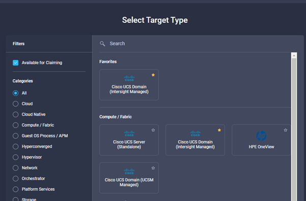
- You’ll need the Device ID and Claim Code from the Device Console. Copy and paste those values into the Intersight claim window shown below:

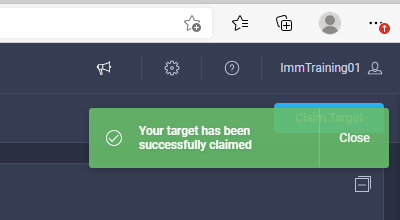
- Click the blue Claim button. Shortly after the claim succeeds, the fabric interconnect Device Connector should show a status of “Claimed” as shown in the following images:

Fabric Interconnect Firmware Upgrade
Before discovering HW attached to the FI’s, it makes sense to get them up to the FW level required. Log in to Intersight with a user with the correct role for upgrading HW, once logged in follow the steps below:
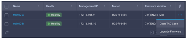
- In Intersight, browse to OPERATE à Fabric Interconnects.
- As shown in the picture below, click the ellipsis (three dots) at the end of the row for either of the fabric interconnects and select Upgrade Firmware. Note: you should step through the wizard to see what the experience is like, but do not click Upgrade on the final step if the target FW version and current version are identical. You will waste a lot of time watching a firmware upgrade process that consumes a lot of time but doesn’t change anything.
- Click Start to bypass the first screen of the firmware upgrade.
- Step one of the upgrade process shows you the current running version for each FI. Click Next.
- Step two of the upgrade allows you to select a different version of firmware. New Fabric interconnects (or those with no discovered chassis) do not need to evacuate server traffic. You must select Advanced Mode and uncheck Fabric Interconnect Traffic Evacuation as shown below:
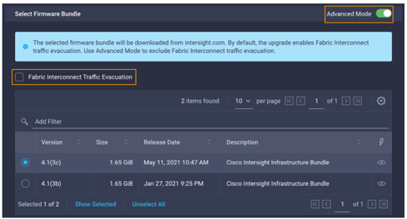
- For this exampled we chose 4.1(3c). Click Next.
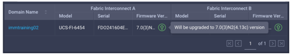
- Step three of the upgrade is simply a confirmation screen that should show both fabric interconnects with their current firmware version and an icon showing the intended firmware version as shown below. The screenshots here might not reflect the latest version numbers as screenshots won’t be updated for every new firmware release. Only click Upgrade if the target firmware version and current firmware version are different. Otherwise hit Cancel.
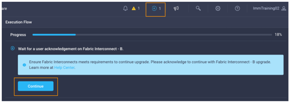
- You will be required to confirm that it is okay to start upgrading the first fabric interconnect as shown below. Click the Continue button and click Continue again on the popup. At this point, the firmware has been downloaded you just approve the process to begin updating the firmware on the first fabric interconnect.
- It will take about 15-20 minutes for the first fabric interconnect to complete its upgrade. You will be required to confirm that it is okay to start upgrading the second fabric interconnect. Much like you did in the previous step, watch for the spinning blue circle to change to a circle with an arrow to indicate that your action is required. Click Continue and click Continue again on the popup.
- It will take about 15-20 minutes for the second fabric interconnect to complete its upgrade. If you browse away from the firmware upgrade status, you can always get back to it by clicking on the spinning blue circle in the Intersight task bar to see current or completed tasks. Browse to OPERATE à Fabric Interconnects to confirm that both fabric interconnects are now running the correct version of firmware.
Visibility during the upgrade process
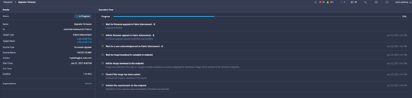
During the upgrade you will see an icon in the top right of the screen, which is a circle spinning, or, if there is a blue arrow you should click on it to see the progress of the firmware upgrade. You will see a window like the one below:
Setting up a Domain Profile in Intersight
The following sections demonstrate HOW to setup a UCS Domain from scratch, including some policies and profiles which are needed.
Introduction
An IMM UCS Domain cannot discover any Servers or Chassis until the ports are configured, which we enable via a domain profile. The benefit of a profile is that it can be repeated so long as the cabling designs are repeated throughout the infrastructure, but even so they do not take very long to create.
The minimum policies required can be seen below, and the subsequent instructions detail the creation of those policies:
- VLAN Policy: Defines the VLANS used. A sub-policy for the multicast configuration is also required
- Port Policy: defined the Ports & Port Channels are configured on a per Fabric Interconnect Model
- NTP Policy: Even if it is just pool.ntp.org
- Network Connectivity: which is effectively DNS Configuration (and Dynamic DNS)
- System QoS Policy: Even if it contains just the defaults

Creating a Domain Profile
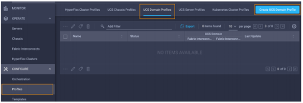
- While logged in to Intersight with the pre-requisite role, choose CONFIGURE à Profiles à UCS Domain Profiles à Create UCS Domain Profile, as shown below:
- A wizard will pop up, click start
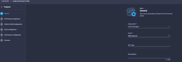
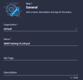
- Give the profile a meaningful name, some tags (if required) and a description. Once this first step is out of the way, you will then assign a physical domain, define the VLANs to be used, ports, and configuration settings for the domain. Click Next.
- You can choose to assign a domain now, or later. Later might be when we are waiting for kit to arrive or be connected to the internet or something.

- Click Next when you have decided to Assign a Domain or do it later.
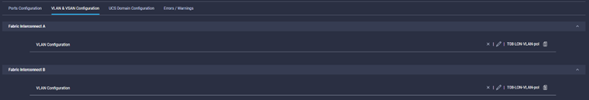
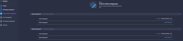
- The next step of the domain creation wizard is VLAN and VSAN configuration, notice that you can apply a different policy to the A and B fabrics. Click Select Policy for the VLAN Configuration for fabric A.
- For inline VLAN Creation click Create New or select an existing policy. To create one, follow the section Policy Create: VLAN Policy.
- Follow a similar procedure for creating a VSAN Policy, we do not show that in this document as the lab doesn’t have an FCoE or SAN Environment, but the principles are the same as traditional UCS. Click Next
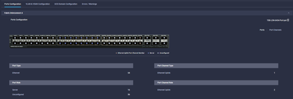
- The next step is to define a port policy, creation of this policy is documented in Appendix A due to the more involved nature of this policy. Either Choose and existing policy or create one inline, once a port-policy is defined or selected, click the next button
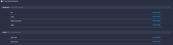
- The last step requires the creation of the NTP, Network Connectivity (DNS), and QoS Policies. You can either select existing policies, or follow the dedicated sections which detail the creation of these policies.
- Click next and confirm that the details in the review screen are accurate:
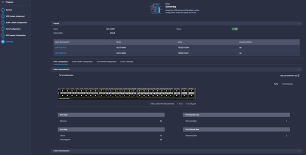
- Click deploy to put the profile into production.
Policy Create: VLAN Policy
- Browse to Configure à Policies à UCS Domain à VLAN and click Start to start the wizard, enter a meaningful name and provide tags and descriptions as required. Click Next
- Click add VLANS
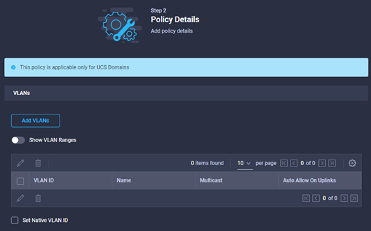
- Add the VLANS, and Ranges

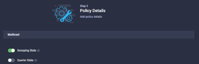
- Add the Multicast policy by selecting the ‘select policy’ button, create a new one or re-use an existing policy. To create a new policy, first give the policy a name, a description and some tags if required. Click next.
- Set the Snooping and Querier state:
Policy Create: NTP Policy
- Browse to Configure à Policies à UCS Domain à NTP and click Start to start the wizard, enter a meaningful name and provide tags and descriptions as required. Click Next
- Enter the NTP servers and the Timezone, then click Create to complete the policy:

Port Policy Creation
Due to the involved nature of a port-policy, please see Appendix A.
Policy Create: SNMP Policy
- Browse to Configure à Policies à UCS Domain à SNMP and click Start to start the wizard, enter a meaningful name and provide tags and descriptions as required. Click Next
- Configure the standard SNMP settings
- Select the platforms, and select the standard SNMP Settings required:

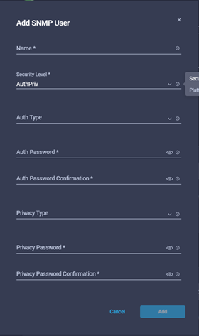
- Click ‘Add SNMP User’ for v3 access:
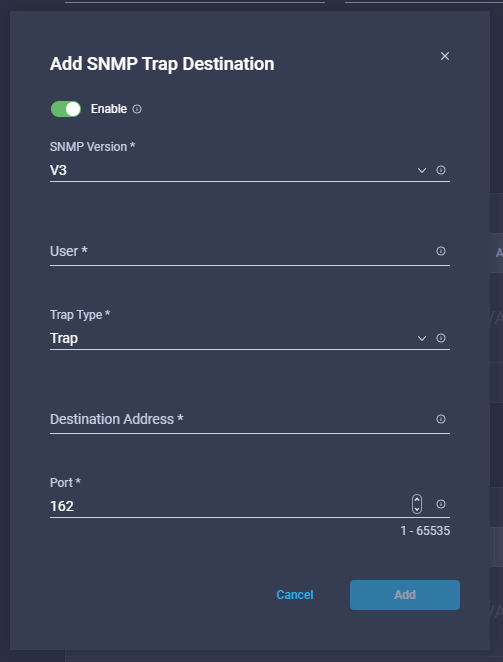
- Define the trap destinations
- Once ready, click create
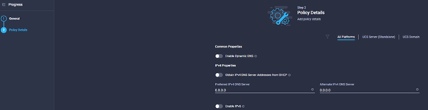
Policy Create: Network Connectivity Policy
- Browse to Configure à Policies à UCS Domain à Network Connectivity and click Start to start the wizard, enter a meaningful name and provide tags and descriptions as required. Click Next
- Toggle the Dynamic DNS Settings button, and define the DHCP for IPv4, Static DNS and IPv6 settings as required. Once completed click Create.
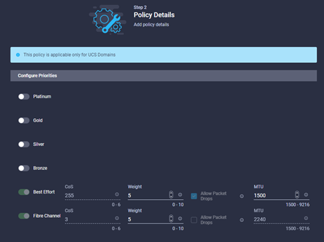
Policy Create: System QoS Policy
- Browse to Configure à Policies à UCS Domain à System QoS and click Start to start the wizard, enter a meaningful name and provide tags and descriptions as required. Click Next
- Configure the relevant settings for the QoS policy, in a lot of environments the defaults are probably OK:
What next?
Any servers or chassis connected to the UCS Domain we just prepared will automatically be discovered, chassis will show up almost instantaneously, but server nodes may take a little longer due to the amount of HW investigation required.
Take a look in the Operate à Chassis section of the GUI to verify the chassis are there.
Next you should create the Service Profiles & Service Profile Templates.
Service Profile Templates
This section describes the steps required to create a service profile template, Intersight has the capability to clone a regular service profile INTO a template, but we will focus on creating a template from scratch.
Templates are groups of policies brought together to form the specifications of a server, before we start the SP Template we should create some policies that will be used in the template upfront:
- The first policy we need upfront is a local user policy, which will allow us to connect to servers using the KVM.
- The other policy is a LAN Connectivity Policy.
Policy Create: Local User
- First step is to browse to the Configure à Policies section of the GUI and click ‘Create Policy’. Select ‘Local User’ policy, click start, and a wizard will pop up.
- Give the policy a name, set some tags and descriptions if they are needed.
- As per the image below, you should note that this policy WILL overwrite any existing accounts EXCEPT for the local admin account, you can disable it by creating an ‘admin’ account and setting this to disabled.
- Enter the relevant information, click ‘Add New User’ and the + sign, enter a username, password and set a role for the user
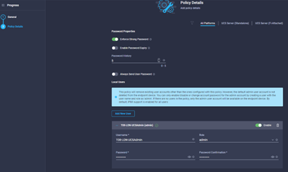
- Select the other properties as required, such as password history, expiry, force strong passwords etc.
- Once complete, click Create.
Policy Create: LAN Connectivity
Due to the potential complexity and involved Nature of creating a LAN Connectivity Policy for vNIC’s, this section is covered in Appendix B.
Service Profile Template Creation
We should now have some of the pre-requisite policies which we will need to complete this template.
- First step is to browse to Configure à Templates, and click ‘Create UCS Server Profile Template’. Give the template a name, select either Standalone or FI-Attached for the target platform, then add some tags and a description where needed. Click next and you should see something like the image below:
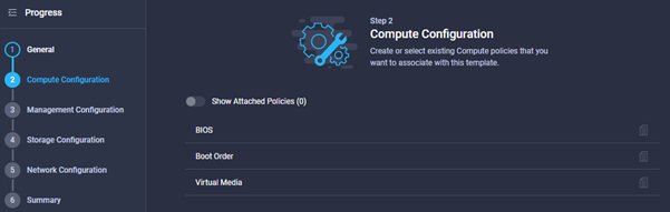
- Step 2 is to provide a policy for BIOS, Boot Order & Virtual Media. We are not going to amend the default BIOS Settings for this guide, but the settings are as per the usual UCS Configuration for BIOS settings including CPU virtualisation, power & performance etc.
- Hover the mouse over the Boot Order and then click ‘Select Policy’, a blade opens from the right and you can either select an existing policy, or you can create new. Click ‘Create New’, see the section ‘Policy Create: Boot Policy’
- Step 3 is configuring management policies, as a minimum we should include ‘Virtual KVM’, ‘IMC Access’ ‘local user’ policies. That said, they are all optional. The policies which can be defined here can be seen below:

- See the sections ‘Policy Create: Virtual KVM’, ‘Policy Create: Local User’, ‘Policy Create: IMC Access’. Once selected, click Next to move to the ‘Storage Configuration’ section
- This template will NOT use local RAID or SD-Cards, so the settings will be left as default, however the document does have the policy definition detailed in Appendix C: Storage Policies
- Click Next to move to the ‘Storage Configuration’ section
- Click Next to move to the ‘Network Configuration’ section
- As mentioned this lab does not have a SAN, so we have not configured the SAN Policy, however, earlier in the document the LAN Connectivity Policy was defined. Select the LAN Policy you created earlier. Click Next to move to the summary page
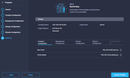
- In the summary page, you can review the settings used by changing the tabs displayed to view the relevant settings. You can then choose to click the derive button, to create the service policies, or just close the window to save the template. The Summary window should look similar to the image below:
Policy Create: Virtual KVM Policy
This policy defines the settings which will be applied to a service profile around KVM. We will enable Virtual KVM, limit connection settings and enforce encryption.
- Browse to Configure à Policies …. And create a Virtual KVM policy
- The first step would be to define a name, description and tags where required.
- Click next which takes you to the policy definition, this should look similar to the image below, select the relevant settings and click create.

Policy Create: IMC Access Policy
This policy defines the settings which will be applied to a service profile around Access to the local IMC on the server where the SP is applied. We will enable set the VLAN ID and define the IP Pool to be used.
- Browse to Configure à Policies …. And create an IMC Access policy
- The first step would be to define a name, description and tags where required.
- The next window should look a bit like the below:
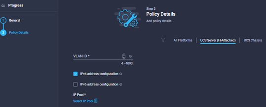
- Define the IP Protocol to be used in this policy.
- Select the IP Pool to be used for the IMC access, if you don’t have a policy already you can define one within the wizard. See the section ‘Pool Create: IP Pool’.
- Once you have created or selected the IP Pool, you will be taken back to the Policy Details section of the wizard, check the settings are correct and click Create.
Pool Create: IP Pool
- Provide a name, tags and description where required, click next, you should see something like the image below.
- Define the settings as required for this IP Pool, for example, this might be used in an IMC Access Policy and therefore will need a pool of IP Addresses for IMC, or for iSCSI Booting.
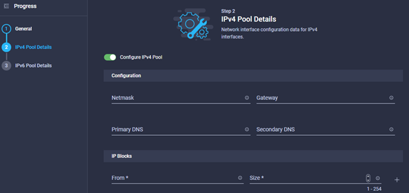
- Once the IPv4 pool is configured, click next and you will be taken to the IPv6 pool.
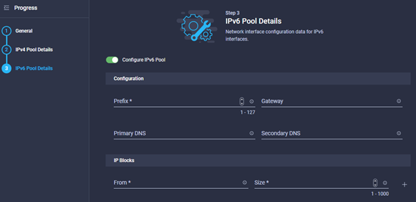
- Either deselect the Configure IPv6 toggle, or enter details. Once completed click Create.
Policy Create: Boot Policy
- Provide a name, tags and description where required, click Next, you should see something like the image below.
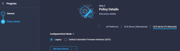
- In this example we are going to Create a policy where the virtual media is the primary boot method, then the local_disk.
- Select the UEFI BIOS, most modern OS’s should support UEFI, toggle the Secure Boot button if needed:
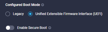
- Click the ‘Add Boot Device’ Button, you will see a drop down menu of boot options like the one in the image below:

- Select Virtual Media, and provide a name for the media device, hold on until you have seen the options in sub-type, this may make you descriptive name better.
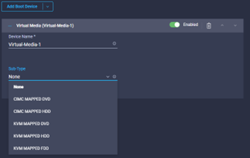
- In this example, we want to select KVM Mapped DVD, so we change the description to KVM-Virtual-DVD, so it’s easy to know what device it is going to use.

- If you envisage having to go directly to the Server CIMC interface, we should also add a CIMC-DVD Virtual Media device also
- Lastly, a Local Disk Selection.
- If you do it in the order described above, you will find that Local_Disk is first, then the CIMC-DVD, and then KVM-DVD. We want the order to be different probably, so use the up and down carat’s on the right of each boot device to select the desired order, once you are happy you will have something which looks like the below:

- Click Create and the policy will be added to your template
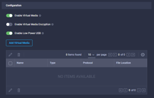
- Next is the Virtual Media Policy. This is important as it differs from traditional UCSM Service Profiles. If we do not have a policy which explicity ENABLES Virtual Media, the Virtual Media will not be mounted.
- The policy is simple to create, click Select Policy, and either select an existing policy, or create new.
- In the create Virtual Media Policy window, provide a policy name, select the tags and provide a description where needed. The default policy looks like the image below, which is usually enough.
- Click create when the options have been configured, and you will be taken back to the ‘Create UCS Server Profile Template’ screen.

Leave a comment