LAN Connectivity policies specify the number and mapping of vnics. It takes several steps, so this guide will walk you through building this policy prior to building a server profile rather than building the policy inline with creating the profile or template.
- Browser the intersight GUI to the Configure à Policies à UCS Server à LAN Connectivity, press the start button, a wizard will open.
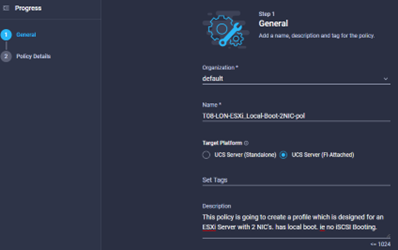
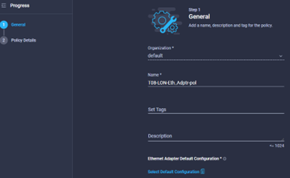
- Enter a meaningful name & define some tags and a description where required.
- This policy can be assigned to either UCS Servers in a standalone configuration, or for servers which are attached to Fabric Interconnects. This guide will describe the FI Attached method, but the standalone mode is not too dissimilar
- Select UCS Server (FI-Attached), provide a name for the policy and select the organisation if this is NOT being used in the default Org. Provide tags and a description is necessary, descriptions are probably required more in this policy than any other due to the critical combination of network connectivity and OS requirements.
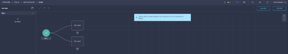
- Once the details have been entered, press next, you should see a screen like the below image:
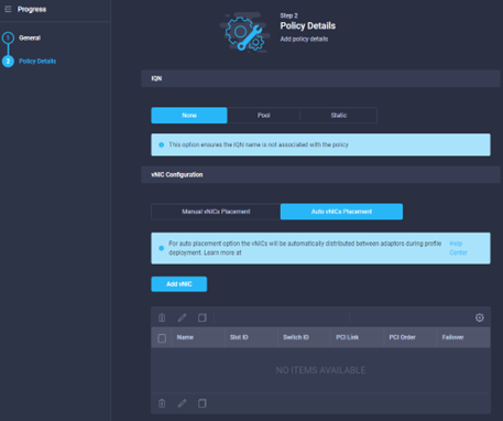
- This example (as the description tells us) will show the creation of 2 vNIC’s with no iSCSI NICS to Boot from, obviously the VIC Card will support many more NIC’s so you should tailor your policy to suit the needs of the intended OS for the template.
- Select NONE in the IQN Setting (this will be covered in a later section)
- Select either Manual or Automatic NIC Placement, Automatic covers most requirements, but ‘Manual’ gives you control over slot/PCI bus detection which is handy for some OS’s.
- See the section ‘Create Policy: vNIC Policy’ for how to create vNIC’s.
- At the end you will see something like the below:
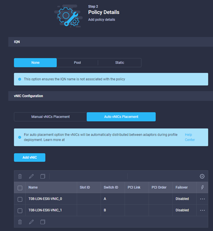
- Click create to create the policy.
Policy Create: vNIC Policy
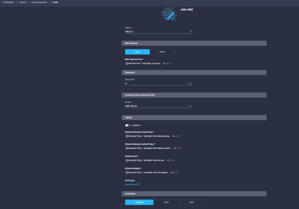
- Select ‘Add vNIC’, another window will open.
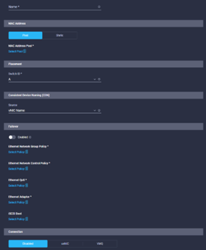
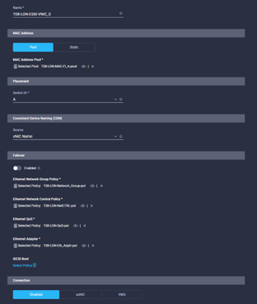
- Let’s start with the Name, enter a meaningful name for the vNIC
- In the MAC Address section, select either Manual or leave the default as pool which is the normal method of deploying UCS with FI.
- In the MAC Address Pool section, click on the Select Pool button, a blade will open from the right, select either an existing pool, or click on create new. We will show the wizard for creating a pool in the section called Pool Create:MAC Address Pool, click create new.
- The next step will be to select the FI, or as Intersight calls them, Switch ID. Select A
- For the Consistent Device Naming, CDN setting, the default is vNIC Name (which is the policy name). You could enter a manual name too, whichever works best for consumption of the policy.
- Depending on the requirements of the OS, you may need this NIC to failover between FI’s or Switches. This LAN Connectivity policy is for ESXi, which handles NIC failure at the Host OS level, we will leave it disabled.
-
The rest of the LAN Connectivity policy is defining other policies which will be used to configure the vNIC, these are detailed in their relevant sections. Policies include:
- Ethernet Network Group Policy
- Ethernet Network Control Policy
- Ethernet QoS
- Ethernet Adapter
- iSCSI Boot
- Once the vNIC policy is complete with the policies required, click ‘Add’
- When creating a LAN Connectivity Policy, you might want to have a vNIC policy for connectivity to both Fabric Interconnects (if the vNIC isn’t going to failover). Repeat the above steps for as many vNIC’s as you need.
Pool Create: MAC Address Pool
- If you are creating this from inline with the LAN Connectivity Policy, In the MAC Address Pool section, click on the Select Pool button, a blade will open from the right, select either an existing pool, or click on create new. Click create new. Otherwise, browse to Configure à Pools à
- Provide a name, tags and description where required, click Next.
- As per a UCSM Deployment, we can use the Cisco OUI of ’00:25:B5:’ or start from scratch. There are MANY theories and strategies for creating MAC Address Pools, in this example we are going to create a simple MAC Pool which will allow us (if required) to configure each blade in this chassis (4 blades) 4 NIC’s on each Fabric Interconnect. Therefore we need 16 MAC Addresses minimum, let’s do 20 just in case. And we will use the Cisco OUI.
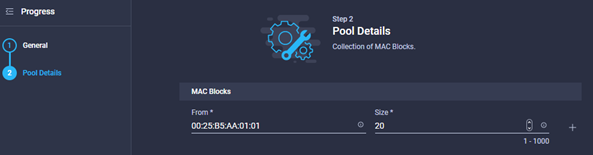
- Notice I can create multiple blocks using the + sign to the right of the first line.
- Click create when the blocks are complete
Policy Create: Ethernet Network Group Policy
Network Group policies essentially detail the VLANS which will be allowed on that NIC, these will have been defined as part of the design workshop
- If you are creating this inline with the LAN Connectivity Policy, In the Ethernet Network Group Policy section, click on the Select Policy button, a blade will open from the right, select either an existing policy, or click on create new. Click create new. Otherwise, browse to Configure à Pools à ****** to create a policy ahead of time.
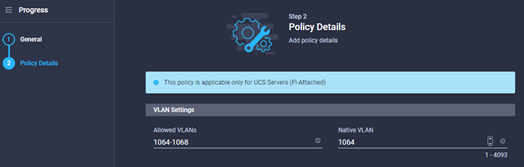
- Provide the policy with a name, tag and description where required.
- Click next and the you will be able to define the Groups, or individual VLANs required on that NIC, and define what is the native VLAN, once completed, click create.
Policy Create: Ethernet Network Control Policy
Network control describes what happens when uplinks go down, discovery protocols etc.
- If you are creating this inline with the LAN Connectivity Policy, In the Ethernet Control Policy section, click on the Select Policy button, a blade will open from the right, select either an existing policy, or click on create new. Click create new. Otherwise, browse to Configure à Pools à ****** to create a policy ahead of time.
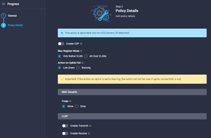
- Provide the policy with a name, tag and description where required.
- Configure the policy details as required, mostly the defaults are OK, but some sort of discovery method is probably recommended. Once complete click Create.
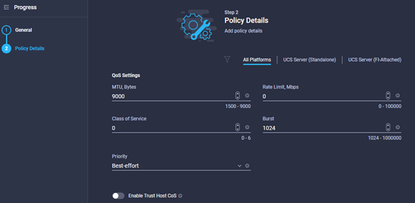
Policy Create: Ethernet QoS Policy
QoS Policy includes MTU settings, Rate limits & Priorities etc.
- If you are creating this inline with the LAN Connectivity Policy, In the Ethernet QoS Policy section, click on the Select Policy button, a blade will open from the right, select either an existing policy, or click on create new. Click create new. Otherwise, browse to Configure à Pools à ****** to create a policy ahead of time.
- Provide the policy with a name, tag and description where required.
- Configure the policy details as required, mostly the defaults are OK, but some sort of discovery method is probably recommended. Once complete click Create.
Policy Create: Ethernet Adapter Policy
Ethernet Adapter policies define how the Physical HW interoperates with the Northbound OS.
- If you are creating this inline with the LAN Connectivity Policy, In the Ethernet Adapter Policy section, click on the Select Policy button, a blade will open from the right, select either an existing policy, or click on create new. Click create new. Otherwise, browse to Configure à Pools à ****** to create a policy ahead of time.
- Provide the policy with a name, tag and description where required.
- Unlike the other LAN Connectivity Policies, for the network adapter we have to define which is the Default Configuration for the Adapter:
- Click the ‘Select Default Configuration’ button, and a blade will open from the right with some pre-defined configurations for the NIC. If you are unsure which one to use, click on the ‘eye’ icon to the right of the description which will detail the exact default HW configurations which will be applied (you will get to adjust them in the next step).
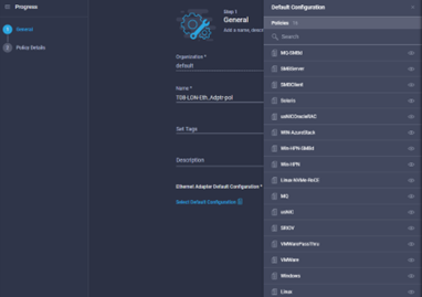
- The policy is for an ESXi Host, so we selected VMware. Click Next.
- As you can see in the illustration below, you are able to tailor the default configuration to suit the needs of the Host OS & Project.
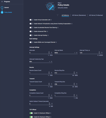
- Normally the defaults are OK, maybe the VXLAN, RoCE or ‘Receive Side Scaling’ settings might need enabling. Once completed click Create.
Graphic vNIC definition:
During the LAN Connectivity Policy definition, you have the option of creating vNIC’s in either a list mode or in graphic mode. The principles are the same, but the GUI definition might make the process of visualising the host connectivity requirements slightly simpler. It is not covered in this guide, but you should know the option exists, some screenshots below show some of the functionality.

Leave a comment